How to Connect RF Module? Correct Setup Guide with Arduino
How to Connect RF Module? Correct Setup Guide with Arduino
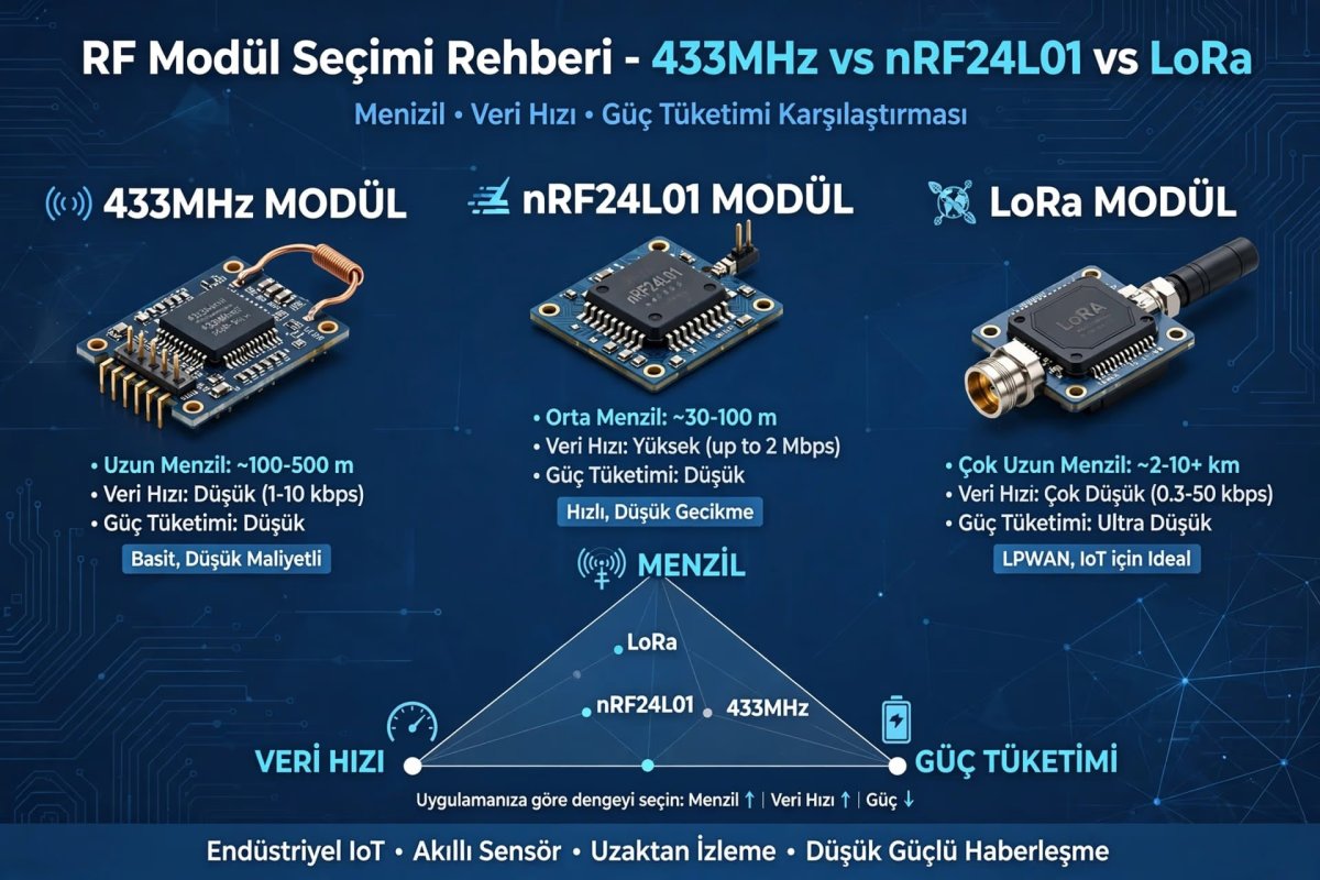
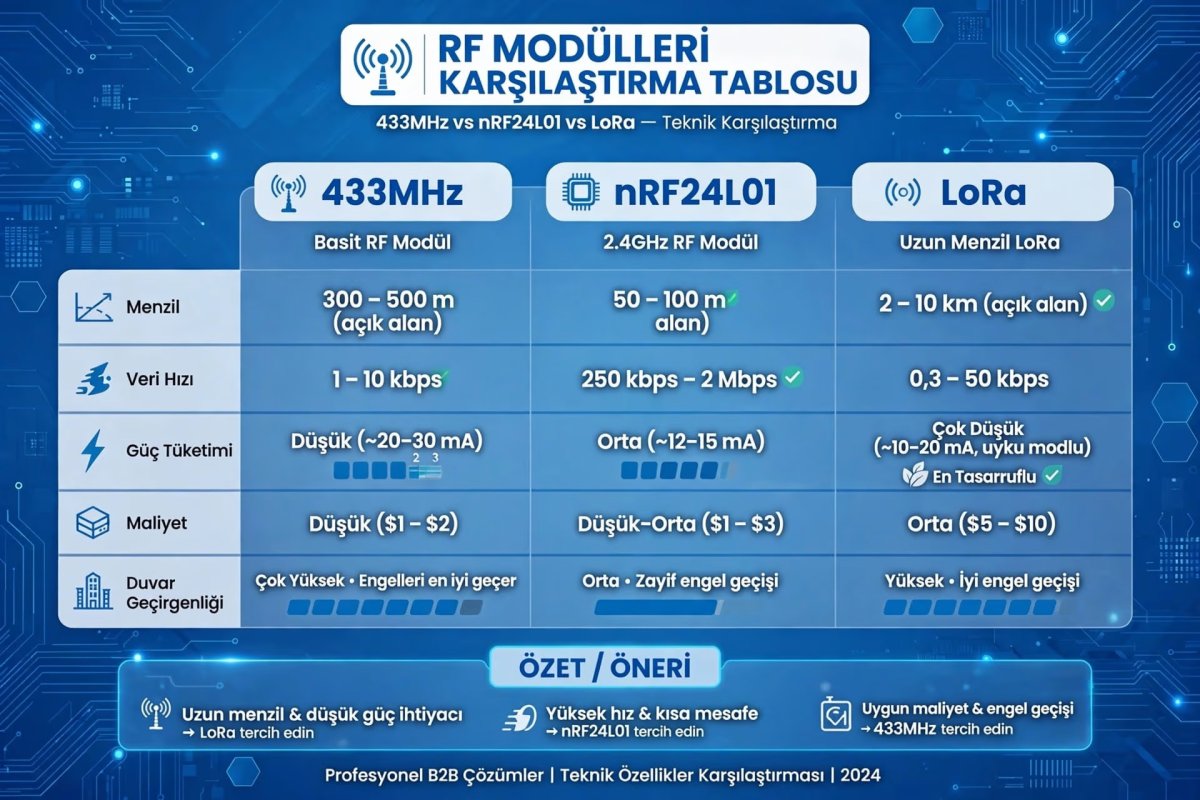
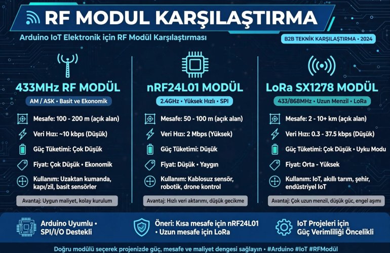
After Choosing RF Module, Correct Connection and Setup Guide90% of those who say "I bought RF module but it doesn't work" are not making mistake in module, but in connection.Choosing RF module is half of job, correct setup is other half. Wrong voltage, use without antenna or GND error drops range from 100 meters to 2 meters.
In this guide we explain correct connection of 433MHz RF modules step by step.What is RF Module Pin Structure?
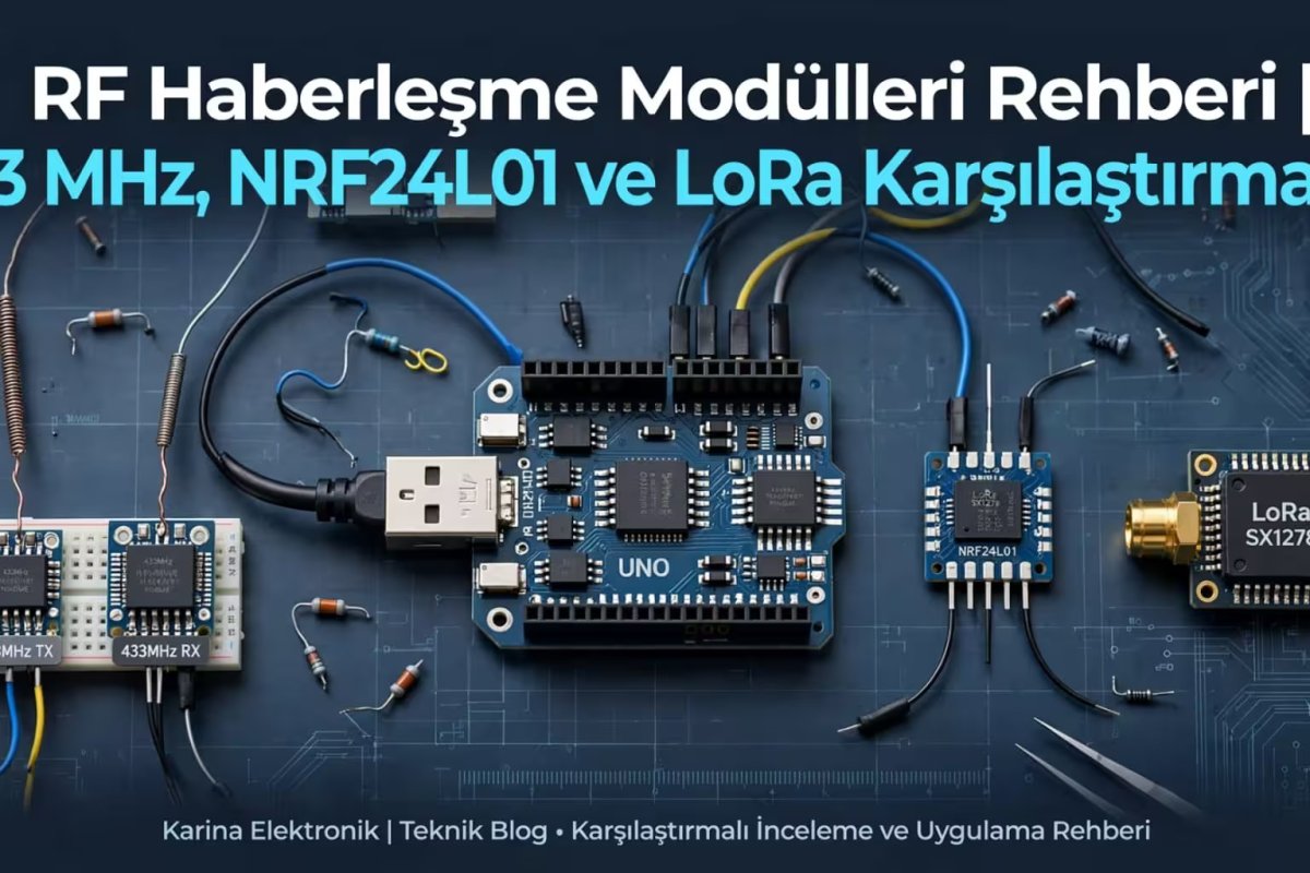
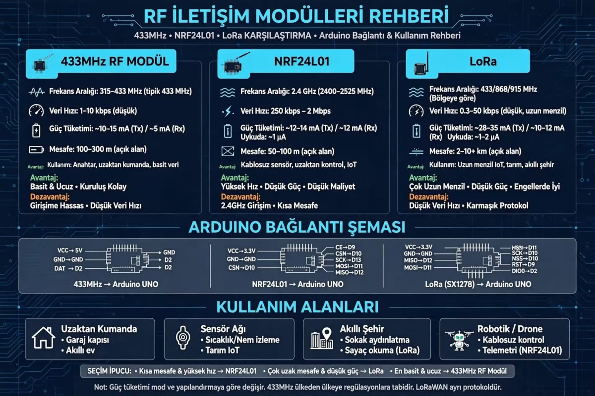
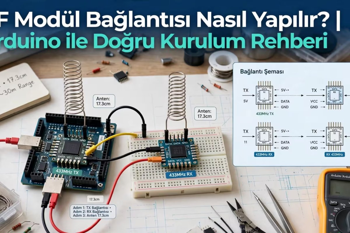
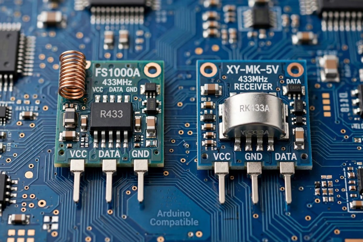
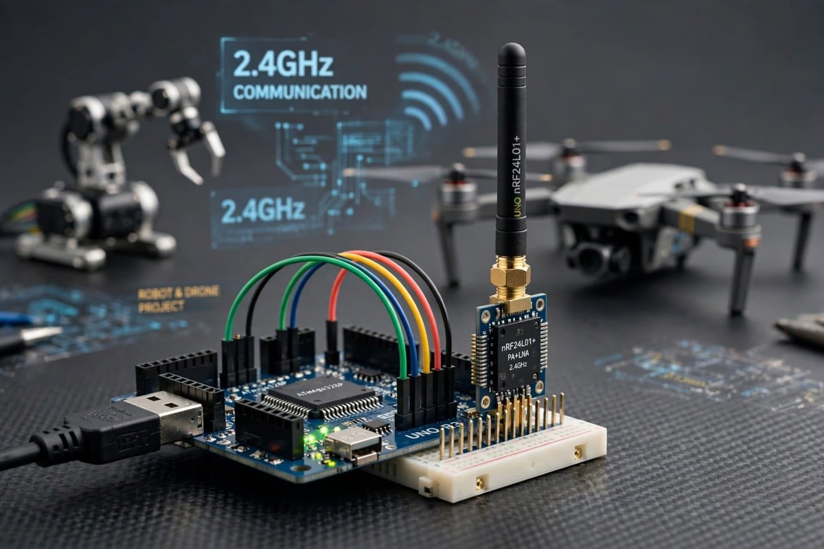
In standard 433MHz modules on market there are 4 basic pins:VCC: Supply. Very critical! Some like FS1000A want 3.5V-12V, RX modules like XY-MK-5V want 5V. Do not give 5V without looking at datasheet.GND: Ground. Must be common in TX and RX circuit.DATA: Pin where data is sent / received. Connects to digital pin of microcontroller.ANT: Antenna pin. If you leave empty, range drops 80%. For 433MHz, 17.3cm single core cable is enough.TX and RX LogicSystem has 2 parts:Transmitter (TX - Transmitter): Scatters 1 and 0 coming from microcontroller (Arduino, ESP32) into air as RF wave with ASK modulation.Receiver (RX - Receiver): Converts RF wave in air back to 1 and 0 digital data.Correct Connection Diagram with ArduinoMost used setup:TX Module (FS1000A / Similar) Connection:VCC -> Arduino 5V (If module supports 5V)GND -> Arduino GNDDATA -> D12ANT -> 17.3cm cable antennaRX Module (XY-MK-5V / Similar) Connection:VCC -> Arduino 5VGND -> Arduino GNDDATA -> D11ANT -> 17.3cm cable antenna
CRITICAL WARNING: If TX and RX are on different Arduinos you don't have to make GNDs common, but if they work in same circuit, common ground is mandatory!Simple Working LogicUse RadioHead or RC-Switch as library. TX side sends with my Switch.send("1010"), RX side listens continuously and decodes data when matched.Most Common 4 Deadly Mistakes
1. Wrong Voltage Usage: If you give 5V to a 3.3V LoRa or CC1101 module it burns instantly. Always datasheet!
2. Use Without Antenna: If no antenna, module writing 100m stays at 3-5 meters. Antenna cost is 0 TL, range increase 10x.
3. Missing GND Connection: Without common GND, data is not perceived as 1, system receives meaningless data.
4. Weak Power Supply: If you feed 2 RF modules and relay from Arduino's 5V pin, voltage drops. Use external stable 5V adapter.How to Test and Check?Do not go directly to project after setup:Print incoming data on RX side with Arduino Serial Monitor.Connect LED to DATA pin, blink when data arrives.First send Hello World, then move to your own protocol.ConclusionRF module setup is not complicated but wants detail.
Correct voltage + solid GND + correct antenna = trouble-free 100 meter wireless communication.You can find tested RF modules, antennas and Arduino compatible sets with delivery time at Karina Elektronik.
For RF modules: https://www.karinaelektronik.com/